
Front Brakes
Les Freins Avant

 |
 |
 |
 |
 |
 |
|---|
BRAKE SYSTEM - GENERAL DESCRIPTION
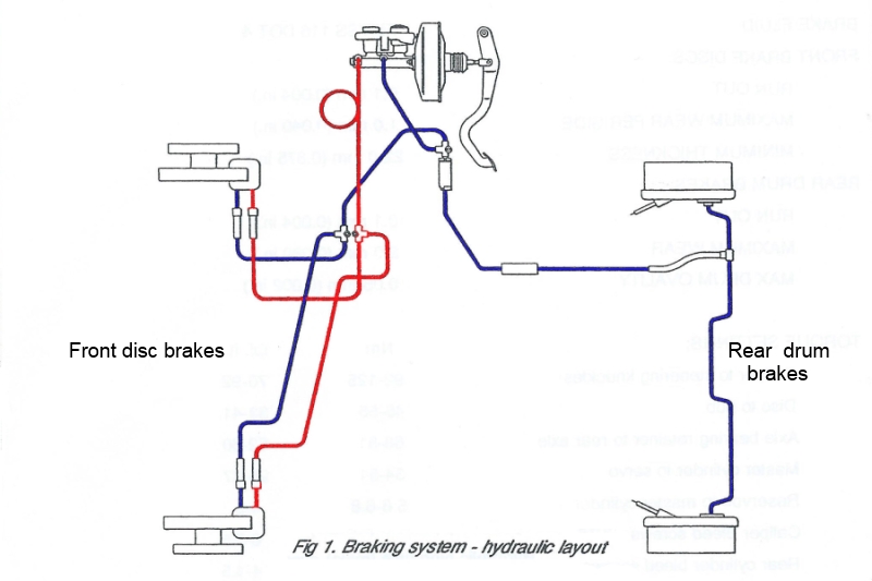
The dual line hydraulic braking System is operated by a vacuum servo assisted tandem master cylinder located on the engine bulkhead. The 278 mm (10.9 in.) ventilated disc front brakes with 4 - pot brake calipers are complemented by 254 X 70 mm (10 X 2.75 in.) self adjusting drum rear brakes.
Rear brake adjustment is achieved by means of a linkage within each rear brake assembly which operates a ratchet to progressively take up excessive brake shoe travel as the brake linings wear in service.
The primary brake hydraulic circuit is connected to one set of opposing cylinders in each front brake caliper and to both rear brakes, the rear brake pipe incorporating a PRV (pressure reducing valve) to reduce the possibility of rear wheel lock up.
The secondary brake hydraulic circuit is connected to a second set of cylinders in each front caliper. This 'H + I' hydraulic layout provides braking effort to both front brakes from both the primary and secondary circuits in the System.
One of the pads fitted to the right hand caliper incorporates wiring which illuminates a warning lamp on the facia when the brake pads require replacement. The hand brake is cable operated.
The engine mounted vacuum pump is connected through an in-line non return valve to the brake servo unit, and incorporates a sensor to operate a warning light in the event of failure. The servo unit will provide servo assistance for a number of brake applications should the vacuum pump fail, after which braking effort is still available without assistance.
Also see: Brakes and Brakes (Fairway 1989-1992)
and "Spares" Brakes (Fairway 1989-1992)

FRONT BRAKE PADS
REMOVE/REPLACE/EXAMINE
NOTE: BRAKE PADS MUST ALWAYS BE REPLACED IN AXLE SETS USING THE NON ASBESTOS REPLACEMENT BRAKE PADS SPECIFIED BY THE MANUFACTURER. NEVER REPLACE BRAKE PADS INDIVIDUALLY OR AS A SINGLE WHEEL SET. SERIOUS CONSEQUENCES COULD RESULT FROM OUT OF BALANCE BRAKING DUE TO A MIX OF BRAKE FRICTION MATERIALS
1. Apply the hand brake and chock the rear wheels. Remove the front hub caps and partly release the front wheel nuts. Raise the front of the vehicle and support it on stands placed under the chassis members. Remove the road wheels.
2. Disconnect the plug of the lead to the brake wear sensor fitted to the inner brake pad of the right hand side brake by pressing the square sides of its socket to release the latches on the side of the plug.
3. Working on one caliper at a time, clean the outside of the caliper assembly (use methylated spirit and a wire brush if necessary to move excessive road dirt).
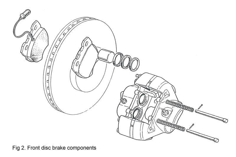
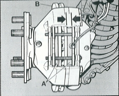
4. Remove the two split pins which secure the pad retaining pins. Withdraw the retaining pins and springs. Lift the pads out of the caliper assembly.
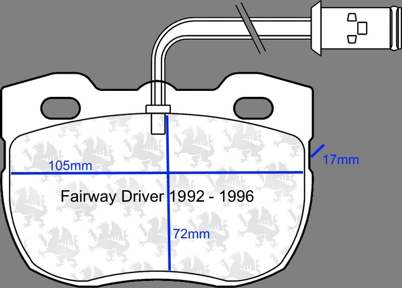
5. Examine the brake pads. Regardless of the state of wear, the pads must be replaced if there is any sign of cracking between the friction material and the metal backplate. If the friction material has worn down to 3mm (0.125 in.) the pads must be replaced.
6. Fit the brake pads into the caliper assembly - the pad with the sensor leads should be fitted to the inside of the right hand brake assembly and the sensor plug reconnected.
NOTE: When new pads are replacing well worn pads it will be necessary to carefully press the brake pistons into the caliper housings. During this operation brake fluid will be displaced. To prevent the reservoir overflowing, fit a bleed tube to the relevant brake bleed screw and release the brake fluid into a container. Retighten the bleed screw when the pistons are fully retracted. Discard the removed brake fluid.
Check the bearing edges of new pads for blemishes (high spots on the steel pressure plates may be carefully removed with a smooth file).
7. Refit the pad retaining springs and springs. Secure the retaining pins with split pins using new parts as required.
8. Repeat operations 3 - 7 for the other side of the vehicle.
9. Refit the front road wheels tightening the securing nuts as much as possible.
10. Lower the vehicle and torque the wheel nuts to specification (torque 200 Nm, 150 Ibf. ft). Replace the hub cap.
11. Operate the foot brake to 'bed' the brake pads. Check the brake fluid level in the fluid reservoir and correct as necessary. Always use new brake fluid to specification FMVSS 116 DOT 4.
NOTE: Remember new brake pads may take several hundred miles to fully 'bed in'. The 'bedding in' process will be extended if the brake discs are not in good condition.
FRONT BRAKE DISC
REMOVE/REPLACE
1. Remove the hub cap and partly release the wheel nuts. Chock the rear wheels. Raise the front of the vehicle and support it on stands placed under the chassis members. Remove the road wheel.
2. Make a suitable wire support for the brake caliper assembly and hang the support on the chassis side member behind the front suspension. Remove the two bolts securing the brake hose securing bracket to the steering knuckle. (When working on the right hand side, remove the brake pad wear sensor lead plug by pressing the square sides of its socket to release the latches on the side of the plug. The earth lead for the sensor is under the head of the hose securing bracket inner bolt). Remove the two bolts securing the caliper assembly and carefully hang the assembly on the wire support so that the brake hoses are not stressed and the caliper is not damaged.
3. Remove the hub dust cap with a suitable lever. Remove the split pin, nut retainer, hub bearing nut and tab washer.
NOTE: The hub bearing nut should normally be at most just finger tight.
4. Carefully pull the hub and disc assembly from the steering knuckle spindle to release the outer hub cone, and remove the hub and disc assembly.
5. Support the hub assembly in a road wheel to allow the brake disc cap screws to be removed and discarded. Check the disc mounting surface is clean and free from burrs and imperfections before fitting a new disc with new cap-screws (torque 45-55 Nm, 33 - 41 lbf.ft).
NOTE: Brake disc wear must not exceed 1 mm (0.040) on either side of the disc, and disc thickness must not be less than 22mm (0.0875 in.) Brake discs may not be reground in service.
6. Fit the hub, outer bearing, tab washer, and hub nut.
7. Use a suitable torque wrench to tighten the hub nut to 7 Nm. (5 lbf.ft). while spinning the hub.
NOTE: Do not over tighten the hub nut as this could cause permanent damage to the hub bearings.
8. Slacken the hub nut without disturbing the hub. Tighten the hub nut again, FINGER TIGHT ONLY.
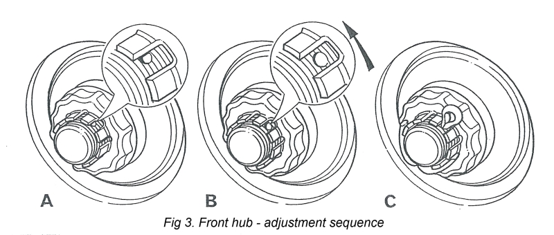
9. Fit the hub retainer without disturbing the hub nut so that one of the tabs on the retainer partly covers the left hand side of the split pin hole in the stub axle (see Fig 3. illustration A).
10. Slacken the nut and nut retainer until the split pin hole is fully exposed (see Fig 3. illustration B), to give the correct bearing end float of 0,025 - 0,152 mm (0.001-0.006 in.)
NOTE: Never set the front wheel bearings too tight; the bearing nut should be loose after following this setting procedure. Correctly set the bearings should have just perceptible end float - if in doubt check the end float with a dial gauge.
11. Fit a new split pin, and replace the hub dust cap.
NOTE: If a new brake disc has been fitted, the brake disc run out must be checked with a dial gauge. Brake disc run out must not exceed 0,1 mm, 0.004 in.
12. Check the brake pad wear and replace the pads as necessary. Refit the brake calipers and torque the two caliper securing bolts to specification 95 -125 Nm, 70 -92 lbf.ft. Remove the wire caliper support.
13. Replace the brake hose securing bracket and earth lead (RHS only), ensuring the brake hoses follow their natural curve clear of the suspension. Refit the brake pad wear sensor lead plug (RHS only).
14. Refit the road wheel tightening the securing nuts as much as possible.
15. Lower the vehicle and torque the wheel nuts to specification (torque 200 Nm, 150 Ibf. ft). Replace the hub cap.
16. Start the engine and pump the brake pedal to position the brake pads to their correct position.
Stop the engine.

.jpg)
FRONT BRAKE CALIPERS
REMOVE/REPLACE/OVERHAUL
NOTE: THE CALIPER UNIT IS SERVICED AS A COMPLETE ASSEMBLY, LESS BRAKE PADS. DO NOT ATTEMPT TO SEPARATE THE TWO HALVES OF THE CALIPER ASSEMBLY TO REPLACE THE PISTON SEALS.
1. Remove the brake pads as previously described. Place a receptacle under the caliper to receive any displaced brake fluid. Remove the bolts securing the caliper assembly to the steering knuckle, disconnect and plug the hydraulic pipes to prevent dirt ingress and fluid toss, and remove the caliper assembly. If the caliper assembly is to be overhauled, thoroughly clean the outside of the caliper assembly and the pad recesses using methylated spirit or brake fluid. If the caliper assembly is to be replaced, proceed to operation 9.
2. Use the special tool MS 331 to hold two adjacent pistons into the caliper body. Place a suitable block of wood into the caliper recess to hold one of the remaining pistons.
NOTE: CARE SHOULD BE TAKEN WHEN CARRYING OUT THE NEXT OPERATION TO ENSURE THE FINGERS ARE NOT TRAPPED AS THE PISTONS ARE EJECTED FROM THE PISTON BORES.
Place a rag into the brake caliper recess to protect the unsupported piston. Apply gentle air pressure from an air line to the brake pipe orifice leading to the unsupported piston to eject the piston from its bore until it is sufficiently exposed to allow it to be removed by hand.
NOTE: If any of the pistons is seized, the complete caliper assembly must be replaced.
3. The wiper seal can be removed by inserting a blunt screwdriver between the retainer and the seal to prise the retainer carefully from the mouth of the piston bore. Taking great care not to damage the seal grooves in the cylinder bore, extract the wiper seal and the fluid seal.
4. Thoroughly clean the bore, piston and the seal grooves with new brake fluid or methylated spirit. If the caliper or piston is corroded, or their condition is not perfect, the parts must be replaced.
5. Coat the new fluid seal with Lockheed Disc Brake Lubricant Ease the seal into. the groove in the bore using only the fingers, ensuring that it is correctly seated into the groove. The fluid seal groove and the seal are not the same in section, thus when bedded the seal feels proud to the touch at the edge furthest from the mouth of the bore.
6. Slacken the relevant bleed screw on the caliper one complete turn and after lightly coating the piston with Lockheed Disc Brake Lubricant. Insert it squarely into the bore using only the fingers. Do not tilt the piston during insertion and leave approximately 8 mm (5/16 in.) protruding from the mouth of the bore.
7. Coat a new wiper seal with Lockheed Disc Brake Lubricant and fit it into the new seal retainer. Slide the assembly squarely, seal first, over the protruding piston and up to the bore mouth. Carefully push home the seal retainer and the piston using the special tool MS 331. Tighten the bleed screw.
8. Repeat operations 2 - 7 for each of the other pistons.
9. Refit the brake calipers and torque the caliper securing bolts to specification 95 -125 Nm, 70 - 92 lbf. ft Reconnect the brake pipes. Fit new brake pads into the caliper assembly as previously described - the pad with the sensor leads should be fitted to the inside of the right hand brake assembly and the sensor plug reconnected.
NOTE: BRAKE PADS MUST ALWAYS BE REPLACED IN AXLE SETS USING THE NON ASBESTOS REPLACEMENT BRAKE PADS SPECIFIED BY THE MANUFACTURER. NEVER REPLACE BRAKE PADS INDIVIDUALLY OR AS A SINGLE WHEEL SET. SERIOUS CONSEQUENCES COULD RESULT FROM OUT OF BALANCE BRAKING DUE TO A MIX OF BRAKE FRICTION MATERIALS
10. Bleed the braking System (see Brake Bleeding procedure).
11. Refit the front road wheels tightening the securing nuts as much as possible.
12. Lower the vehicle and torque the wheel nuts to specification (torque 200 Nm, 150 lbf. ft). Replace the hub cap.
13. Operate the foot brake to 'bed' the brake pads. Check the brake fluid level in the fluid reservoir and correct as necessary. Always use new brake fluid to specification FMVSS 116 DOT 4.
10. NOTE: Remember new brake pads may take several hundred miles to fully 'bed in'. The 'bedding in' process will be extended if the brake discs are not in good condition.
NOTE: The newer caliper assembly sold for P-reg Fairway Drivers and TX1s can be retrofitted onto older Fairways (1992-1996), provided the matching brake pads and pin kits are renewed together.
FRONT BRAKE HOSES
1. Apply the handbrake and chock the rear wheels. Relieve the vacuum from the serve unit by operating the brake pedal several times. Remove the front hub caps and partly release the front wheel nuts. Raise the front of the vehicle and support it on stands placed under the chassis members. Remove the road wheels.
2. Place a suitable drain tray below the front brake hose connections. Disconnect the brake hydraulic pipes from each end of the hoses and plug the brake pipes to prevent dirt ingress.
NOTE: The front brake hoses are similar to each other and are fitted so that ends with the rubber reinforcement sleeves are fitted towards the calipers. The two brake hoses each side of the vehicle are routed forward from the support bracket on the steering knuckle to form a natural curve before entering the support bracket on the top of the front crossmember from front to rear. The end fittings of the hoses are 'D' shaped and fit into 'D' shaped holes in the support brackets so that the natural curve is retained once the securing clips have been positioned. The primary circuit hose leading from the front mounting point on the steering knuckle hose support bracket is routed to the lower of the two hose mounting holes in the support bracket on the crossmember. Conversely, the secondary circuit hose leading from the rear mounting point on the steering knuckle support bracket is routed to the upper hole in the support bracket on the crossmember. This routing of the hoses is critical to the correct operation of the brakes.
3. Remove the spring clips which secure the ends of the hoses in the support brackets. Discard the hoses and replace any clips which may be damaged.
NOTE: The tie securing the lead to the brake pad wear sensor to the secondary hose on the right hand side of the vehicle should be cut so that the hose can be removed.
4. On one side of the vehicle, fit the ends of the new brake hoses (without the rubber reinforcing sleeves) to the upper hose support bracket mounted on the crossmember and secure with the spring clips.
NOTE: In service the clips may be fitted in towards the centre of the vehicle provided the outer edge of each clip is positioned parallel to the edge of the support bracket. Ensure each clip is pushed fully home into its recess in the hose pipe end fitting. Route the end of the hose leading from the upper position in the crossmember hose support bracket in a natural curve round and down to the rear hole on the support bracket attached to the steering knuckle, and secure it with a clip. Similarly route the other hose to the front hole in the tower support bracket. Ensure each clip is pushed fully home into its recess in the hose pipe end fitting. Reconnect the hydraulic pipes at each end of each hose. Repeat the procedure on the other side of the vehicle. Use a new tie to secure the lead to the brake wear sensor to the secondary hose on the right hand side of the vehicle.
5. When all other work on the braking System has been completed, bleed the hydraulic System thoroughly using new brake fluid which complies with the specification FMVSS 116 DOT 4 (see: Brake Bleeding). Apply the brake pedal several times to automatically adjust the brake shoes and obtain the correct running clearance. Top up the master cylinder reservoir to its correct level before road testing the vehicle.
WHERE TO BUY THE SPARE PARTS
Front brake disc
London Taxi Parts
one unit £18.60
Front brake pads (Fairway Driver from J-reg up to P-reg)
London Taxi Parts
one set £15.00
Front brake pads (Fairway Driver P-reg, TX1, TX2, Metrocab TTT)
London Taxi Parts
one set £15.00
Front brake pad pin kit (Fairway Driver from J-reg up to P-reg)
London Taxi Parts
one kit £3.24
Front brake pad pin kit (Fairway Driver P-reg, TX1, TX2, Metrocab TTT)
London Taxi Parts
one kit £3.30
Calliper Piston Repair Kit (Fairway Driver, TX1, TX2, Metrocab TTT)
London Taxi Parts
one kit £22.20
CA827 Brake Caliper Front Axle Left
dusty789blue
one set £77.64
CA827R Brake Caliper Front Axle Right
dusty789blue
one set £75.38
Front flexi pipe (Fairway Driver, TX1, TX2, Metrocab TTT)
London Taxi Parts
one unit £17.40