
Fairway 1989-1992
Early Fairway Brakes

 |
 |
 |
 |
 |
 |
|---|
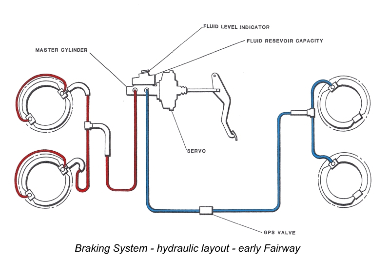
BRAKE SYSTEM - GENERAL DESCRIPTION
The brakes on all four wheels are hydraulically operated by a foot pedal directly connected to the master cylinder.
The handbrake is mounted on the floor of the car convenient to the driver. It is of the conventional ratchet and pawl type, operating on the rear wheels only by means of rods, a compensator mounted on the rear axle, and transverse rods to the brake-shoe levers.
Two leading shoes in each front assembly are expanded by individual, single-acting hydraulic cylinders connected by tubing and bolted to the back plate. Each shoe pivots and slides on one of the cylinders with its opposite end in contact with the piston of the cylinder diametrically opposite. Two pull-off springs are fitted, each connected from one show to the back plate. An adjuster controls the movement of each shoe without interfering with its normal braking function.
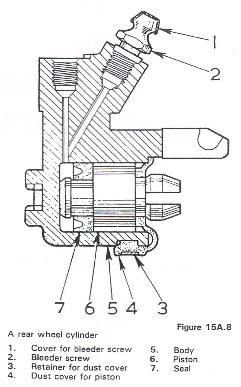
Two shoes, one leading and one trailing, are expanded in each rear assembly by a single-acting hydraulic cylinder and piston assembly floating on the back plate. Two springs are fitted and connected between the shoes. The shoes are not fixed but are able to slide on their abutments and centralize in the drum. At the cylinder end the leading shoe is located in a slot in the piston while the trailing shoe rests in a slot formed in the cylinder body; at the adjuster ends they rest in slots in the adjuster links. The shoes are supported by adjustable steady posts screwed into the back plate.
Inclined inner faces on the adjuster links bear on the inclined faces of the adjuster wedge, which has finely threaded spindle and a squared end projecting through the back plate. Rotating the spindle therefore will expand the shoes or allow them to come together under the influence of the return springs.
The handbrake lever is pivoted in the cylinder body and when operated the lever tip expands the leading shoe independently of the hydraulic piston and the pivot moves the cylinder body to apply the trailing shoe.
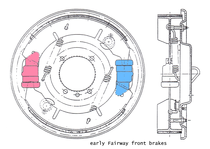
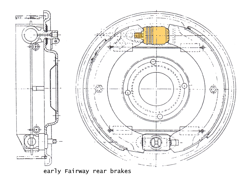
Removing and Replacing a Wheel Cylinder
Front
Jack up and remove the wheel, drum and shoes.
Disconnect the bridge pipe unions from the cylinder.
Unscrew the two securing nuts and remove the cylinder(s).
When refitting, tighten the wheel cylinder nuts to a torque wrench reading of .69 to 1.03kgm (5 to 7.5 lbft).
After refitting bleed the brakes.
Rear
Jack up the wheel and remove the wheel, drum and shoes.
Disconnect the pipe from the union, the rod at the hand brake lever, and remove the rubber boot from the rear of the backplate.
With a screwdriver prise the retainer and spring plates apart and tap the retaining plate from below the neck of the wheel cylinder.
Withdraw the handbrake lever from between the backplate and wheel cylinder.
Remove the spring plate and distance pieces and finally the cylinder from the backplate.
To refit, smear the backplate and cylinder with Girling White Brake Grease and mount the cylinder onto the backplate with the neck through the large slot. Replace the distance piece between the cylinder neck and the backplate with the open end away from the handbrake location; the two cranked lips must also be away from the backplate.
Replace the handbrake lever. Locate the retaining plate between the distance piece and the spring plate (open end towards the handbrake lever) and tap into position until the two cranked lips of the spring plate locate in the retaining plate.
Fit the rubber cover. Connect the pipe to the union and the rod to the handbrake lever. Replace the shoes, drum and wheel.
Bleed and adjust the brakes.
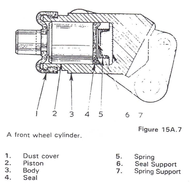
Dismantling and Assembling a Wheel Cylinder
Front
Remove the cylinder.
Remove the rubber dust cover; the piston seal, spreader and spring can be extracted by air pressure.
Rear
Remove the cylinder.
Remove the spring clip and rubber dust cover.
Blow out the piston and seal.
Replacement in both front and rear cylinders is a reversal of the dismantling procedure.
Removing a Flexible Hose
Do not attempt to release a flexible hose by turning either end with a spanner; it should be removed as follows:
Unscrew the metal pipe line union nut from its connection to the hose.
Hold the hexagon on the flexible hose and remove the locknut securing the flexible hose union to the bracket.
Unscrew the flexible hose from the cylinder end.
MASTER CYLINDER
The brake fluid reservoir mounted on the Master Cylinder is divided ínternally, each half having a single outlet to a fluid chamber and piston in the master cylinder.
When the footbrake is applied the primary piston moves up the master cylinder bore and creates pressure in the fluid to operate the wheel cylinders connected to the rear outlet. The piston also continues up the bore to apply pressure to the secondary piston which operates the other two wheel cylinders.
Should failure occur in one circuit, brake pedal travel will increase and the remaining circuit will operate.
Remove
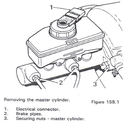
1. Disconnect the electrical warning light connector from the reservoir filler cap.
2. Place a small container beneath the master cylinder and disconnect the two brake pipes.
3. Remove the two retaining nuts and washers and withdraw the master cylinder from off the end of the brake vacuum Servo unit.
Refit
4. Reverse the procedure in operations 1 to 3.
5. Fill the master cylinder reservoir with a recommended brake fluid.
6. Bleed the braking system and top up the cylinder reservoir with brake fluid.
Master Cylinder Overhaul
Dismantle
1. Remove the master cylinder. see 'MASTER CYLINDER - Remove'.
2. Drain any fluid remaining in the reservoir. Plug the pipe connections and thoroughly clean the exterior of the unit.
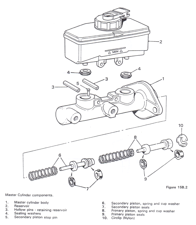
3. Hold the cylinder horizontally in a soft-jawed vice with the reservoir upperrnost, drift out the two hollow retaining pins and remove the reservoir uppermost, drift out the two hollow retaining pins and remove the reservoír from the cylinder; remove the sealing washers from the recesses in the cylinder body, see figure 15B.2.
4. Push the piston in and extract the nylon circlip.
5. Withdraw the primary piston and spring complete with seals, see figure 15B.2.
6. Use a soft metal rod and press down the secondary piston whilst using a pair of pliers to extract the piston stop pin from the recess in the cylinder body, see figure 15B.2. The secondary piston and spring assembly can now be extracted with thin nosed pliers or by tapping the cylinder on a soft or wooden surface.
7. Remove the spring, retainer and seals from each piston keeping the primary and secondary components separate. While both springs may look alike, the secondary piston spring is stronger and has a thicker coil.
Inspect
8. Clean the master cylinder components and check that the inlet and outlet ports are free of obstruction.
9. Check the bore of the master cylinder and renew the assembly if the bore is scored of ridged.
Reassemble
10. Lubricate the cylinder bore, pistons and new seals with clean brake fluid and fit the seals onto the pistons using fingers only, ensure that the seals are fitted as shown in figure 15B.2. Refit the springs to the pistons.
11. Refit the secondary piston assembly into the cylinder bore, taking care not to turn back the lip of the piston seal. Push the assembly down the bore using a soft metal rod, and insert the stop pin, see figure 15B.2.
12. Re?t the primary piston assembly into the bore, taking care not to turn back the lips of the piston seals, push the assembly down the bore and secure with the nylon retaining circlip.
13. Position the two resewoir seals into the cylinder body recesses, refit the reservoir and secure with the two hollow retaining pins.
14. Refit the master cylinder.
15. Bleed the braking system.
WHERE TO BUY THE SPARE PARTS
Front brakes
Jeu de mâchoires de frein Carbodies JHM932
Mister Auto
43,94 Euro
Rear brakes
Jeu de mâchoires de frein Carbodies JHM933
Mister Auto
38,70 Euro
Flexible de frein Carbodies JHM532
Mister Auto
20,27 Euro
Brake master cylinder
Maître cylindre de frein Carbodies PMK183
Amazon
119,42 Euro