
Auto Transmission
La Boîte automatique
 |
 |
 |
 |
 |
 |
|---|
WHICH AUTOMATIC TRANSMISSION ON MY CAB?
FAIRWAY FROM 1989 TO 1996
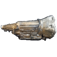
Fairways and Fairway Drivers from 1989 to 1996 (N reg) are equipped with a vacuum controlled Nissan/Jatco E4N71B transmission almost identical to the Nissan/Jatco L4N71B that equips different Nissan or Mazda models.
Transmission filter kit ref.: Beck/Arnley 044-0192 or ATP B-75 or FRAM FT1092
FAIRWAY DRIVER FROM 1997
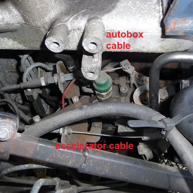
Fairway Drivers from 1997 (P reg, R reg) are equipped with a cable operated Nissan/Jatco RL4R01A transmission, identical to the one that equips TX1 and TX2 taxis, as well as the Nissan Frontier Pick up 2.4L (1995-1997).
Transmission filter kit ref.: Beck/Arnley 044-0289 or AC Delco Pro TF321 or Champion Labs T732

Shape of auto gear box sump Nissan E4N71B

Shape of auto gear box sump Nissan RL4R01A
HOW TO TELL THE TWO AUTO BOXES APART?
1. Look at the vacuum pump on the rear of the alternator: if there are 3 vacuum pipes coming off it, one to the gearbox, one to the servo, and a thin one to the brake boost sensor which is by the engine stay then it is the usual Fairway box (E4N71B), but if there are only 2, one to servo and one to brake boost sensor then it is the later type TX1 electronic box (RL4R01A).
2. Look at the injector pump: if there is a vacuum modulator it's an early Fairway vacuum box and if there is a kick down cable parallel to the accelerator cable then it's a later TX1 box.
3. The shape of the auto box oil sump is different: see above pictures!

early autobox type E4N71B

later autobox type RL4R01A

early autobox type E4N71B
later autobox type RL4R01A
HOW DOES AN AUTOMATIC TRANSMISSION WORK?
- There is no clutch, but a hydraulic torque converter that isolates the engine from the transmission and allows slippage during gear changes;
- the input and output shaft can be placed on the same axis or in parallel according to the box type. (same axis on the Fairway);
- the output shaft has not pinions but cascading planetary gear sets;
- each planetary gear train has its own system of clutch and brake (for decelerations);
- selecting a ratio is made thanks to a system of pressurized oil distribution to the epicyclic train concerned (hydraulic block);
- the oil distribution system includes a high pressure oil pump driven by the engine, a distributor and valves;
- the first generation of automatic transmissions are controlled by mechanical, electromechanical or hydraulic systems. A cable connecting the box to the accelerator, enslaves the box to the engine load. The variable pressure supplied by the pump is proportional to a given engine speed information. These settings allow the control system to trigger shifting as needed.
- modern boxes are managed by an electronic computer. The computer has a number of sensors: accelerator pedal, brake, engine torque, engine speed, vehicle speed, choice of operation of the vehicle (= position of the gear lever) ... allowing a more acute choice of the oil pressure distribution (and therefore gear selection).
Thus we see that the proper functioning of the automatic transmission depends on two parameters:
- the good condition of the automatic transmission;
- a good connection between the engine and the transmission to transmit correct data on the engine load.

Automatic Transmission

Hydraulic Torque Converter
| Gear ratios | |||||
|---|---|---|---|---|---|
| Gearbox type | 1 | 2 | 3 | 4 | R |
| E4B71B | 2.458 | 1.458 | 1.000 | 0.686 | 2.181 |
| RL4R01A | 2.785 | 1.545 | 1.000 | 0.694 | 2.272 |
MAINTENANCE OF THE AUTOMATIC TRANSMISSION
Maintenance of the automatic transmission is accomplished mainly through regular renewal of the transmission oil.
See chapter : GEARBOX OIL- AUTO TRANSMISSION
This is often neglected for as long as the gears shift, we tend to ignore that part of the vehicle!
Yet the oil contained in the box and the torque converter is gradually losing its properties, mostly due to heating after intense and prolonged use of the vehicle.
If we find that the box is slipping at acceleration or gears take an abnormal time to shift, it's time to renew the oil in the transmission.
It is recommended to check the oil level with the engine running, or to check with the engine stopped but only very quickly afterwards because the oil level drops when the engine is running as some is held in the torque converter.
Checking the level on a cold engine can give the impression that the maximum is reached, while oil may be missing in box!
When draining only about 1 liter 1/2 of the fluid comes out of the drain plug while the rest stays in the box and torque converter.
However, the renewal of approximately one quarter of the total oil in the box (7 liters) is usually enough to give back all its features to the box.
In case of doubt, the color, smell and consistency of the oil will tell you about the state of the box.
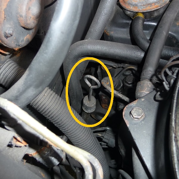
The transmission fluid is to be filled through the neck of the autobox gauge.
See picture on the right for its location: the gauge is situated behind the air filter housing.
WHAT CAN YOU LEARN FROM THE COLOR AND SMELL OF AUTOMATIC TRANSMISSION FLUID?
There's a lot you can learn about the condition of your transmission just by examining the fluid. So checking the fluid's color and giving it a little sniff is a great indication of whether your transmission is in good shape, or in need of service.
Here are the basic conditions you should be looking for:
1. Clean, clear fluid, with virtually no odor
The fluid's like new. Chances are the transmission's working fine.

2. Slight brownish tint, with a lightly burnt odor
The fluid's beginning to burn, and is probably due for a service. If you didn't have the fluid exchanged completely the last time you had the transmission serviced, you may just be looking at the old oil that was left in the transmission. As long as the transmission seems to be working okay, consider a complete fluid exchange service in the not-too-distant future.

3. Brown color, with a distinctly burnt or varnished odor
The fluid's burnt, and you may already be experiencing transmission operating problems. There's little doubt that the transmission is beginning to wear. Eventually you'll be facing a transmission job.

4. Black color, with a bad stench
The fluid's severely burnt, and the transmission probably is, too. You're probably experiencing a serious transmission operating failure. A service at this point will usually be a complete waste of money; the trans is going to need a rebuild. And there's the possibility of related problems, such as a clogged trans cooler or a cooling system problem. Make sure you have these systems checked at the same time, to avoid a second transmission failure.

ON-VEHICLE SERVICE - FAIRWAY & FAIRWAY DRIVER, 1989-1996 (-> 'N' reg)

Vacuum Modulator Rod Adjustment
1. Remove modulator from transmission case.
2. With a depth gauge, measure depth "L". Be sure vacuum throttle valve is pushed into valve body as far as possible.
3. Check "L" depth with chart below and select proper length rod.

Vacuum modulator rod selection
Measured depth "L" mm (in) | Rod length mm (in) | Part number |
Under 25.55 (1.0059) |
29.0 (1.142) |
31932-X0103 |

Downshift Solenoid
Confirm that clicking sound is heard when power is applied. If necessary, remove downshift solenoid and check the operation. Catch oil dropping out of the hole when removing downshift solenoid.

Vacuum Modulator Adjustment (On TD23 and TD27 engines)
1. Loosen the lock nut on the adjusting rod, and adjust the adjusting rod.
2. Install a vacuum gauge between the vacuum pump and the vacuum modulator.
3. Set the parking brake and depress the brake pedal.
4. Start the engine and place the control lever in "2" range.
5. Make adjustments with adjusting rod until the vacuum pressure is as shown in the following chart.
Throttle opening | 2/8 | 4/8 | 6/8 |
Vacuum pressure |
64.0 - 72.0 |
38.7-46.7 |
22.7 - 30.7 |

6. Tighten the lock nut on the adjusting rod.
1.0 - 1.4N-m
(0.1 - 0.14 kg-m, 0.7 - 1.0 ft-lb)
Make sure that the pipe (in green in the picture) that goes from the air cleaner to the vacuum modulator is not broken or missing!

Inhibitor Switch Adjustment (E4N71B Model)
Disconnect harness at connector, then remove inhibitor switch.
. Check continuity at "N", "P" and "R" ranges.
. With selector lever held in "Neutral", turn manual lever an equal amount in both directions to see if current flow ranges are nearly the same. (Current normally begins to flow before
manual lever reaches an angle of 1.5° in either direction.)
If current flows outside normal range, or if normal flow range is out of specifications, properly adjust inhibitor switch.

Adjust inhibitor switch as follows:
1. Place the manual valve in Neutral (vertical position).
2. Remove the screw.

3. Loosen the attaching bolts.
4. With an aligning pin [2.0 mm (0.079 in) dia.], move the switch until the pin falls into the hole in the rotor.
5. Tighten the attaching bolts equally.
6. Recheck for continuity. If necessary, replace the switch.

Position of the kickdown switch.
It is actuated when pressing hard the accelerator pedal.
The switch wires go to the downshift solenoid on the side of the transmission.
The screw above the switch is for adjustment of the accelerator pedal travel.

Transmission Nissan/Jatco E4N71B on Fairway & Fairway Driver, 1989-1996 models
ON-VEHICLE SERVICE - FAIRWAY DRIVER, 1997 ('P' reg & 'R' reg)

Kick-down Cable Adjustment, Transmission Nissan/Jatco RL4R01A
Kick-down Cable Adjustment
1. Slacken both lock nuts N1 & N2 to extreme ends of threaded outer cable Q.
2. Block injector pump throttle lever R at full-throttle.
3. Pull outer cable threaded portion Q fully in direction T.
4. Tighten nut NI1 in direction U until it contacts back of bracket S.
5. Immediately slacken nut N1 by 1 to 1 1/2turns.
6. Hold nut N1 with a spanner so that it does not move from position set in operation 5.
7. Tighten nut N2 until it contacts bracket S.
8. Fully tighten nut N2.
9. Unblock throttle lever R.
10. Check stroke of kick-down cable between idle position P2 and full throttle position P1. This should be 41 mm ± 2 mm.

Kick-down Chart
If the kick-down cable is incorrectly adjusted the following problems may occur.
. If the kick-down cable full throttle position P1 is set towards direction T, the shift schedule will function as shown by line (1) in illustration at left.
. If the kick-down cable idle position P2 is set towards direction U, the shift schedule will function as shown by line (2) in illustration at left.
It is possible to adjust the shift pattern to individual requirements by adjusting the cable by small increments. Never move the cable lock nuts by more that 1/2 turn at a time. Never move the adjustment by more than a total of 2 full turns in each direction from the original adjustment position. Transmission internal pressures are affected by running with the kick-down out of adjustment, resulting in serious and premature damage.

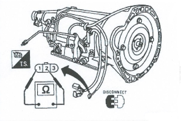
Electrical Inspection of Overdrive Cancel Solenoid
. Check resistence between terminals of each solenoid.
Resistance: 20 - 30 Ω
| Solenoid | Terminal N° | Resistance |
|---|---|---|
| O.D. Cancel Solenoid | (1) - (2) | 20 - 30 Ω |

Electrical Inspection of Inhibitor Switch
1. Check continuity between terminals (1) and (2) between terminals (3) and (4), (5), (6), (7), (8), (9) while moving selector lever through each range.


RL4R01A - Remove the shift control linkage
Inhibitor Switch Adjustment (RL4R01A Model)
The switch unit is bolted to the the transmission case, behind the transmission shift lever. The switch prevents the engine from being started in any transmission position except P or N. It also controls the reverse light.
1. Disconnect the shift linkage at the switch assembly

RL4R01A - Insert the pin through the two adjustment holes
2. Place the transmission selector lever in the N position.
3. Loosen the switch mounting bolts.
4. Insert a 4.0mm aligning pin into the adjusting holes in both the switch and the manual shaft so that it is as vertical as possible.
5. Tighten the mounting bolts equally, connect the shift linkage and remove the pin.
6. Make sure while holding the brakes on, that the engine will start only in P or N. Check that the reverse light goes on only in R.

Neutral Safety Switch on the car

Neutral Safety Switch spare part

Transmission Selector
Manual Central Linkage Adjustment
Move the selector lever from 'P' range to '1' range. You should be able to feel the detents in each range. The control should move smoothly and without resistance except for the operation of the detents.
Put the floor selector lever in 'N'.
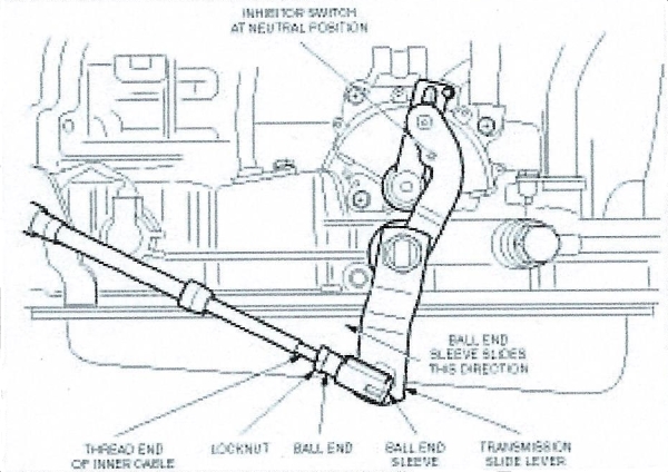
RL4R01A - Selector Linkage Adjustment
Underneath the vehicle:
1. Slacken the lock nut at the ball end of the selector cable.
2. Slide back the sleeve on the ball end of the selector cable and pull the ball housing off the ball.
3. Ensure that the transmission side lever is in 'N' position.
4. Turn bail housing on end of selector cable until it locates on ball on transmission side lever without resistance.
5. Refit the ball housing and ensure the sliding sleeve is fully in place.
6. Tighten the lock nut at the ball end of the selector cable.

Transmission Nissan/Jatco RL4R01A on Fairway Driver, 1997 model
REAR GEARBOX MOUNT

Engine mounts
The engine and gearbox are attached to the chassis by 3 rubber/metal bearings. The rear engine mount is indeed the one that supports the rear part of the transmission on the crossmember.

1989-1996 Fairway rear engine mount

1997 Fairway / TX1 / TX2 rear engine mount
Part reference: 800986.
Part references: FEM4062, BEM4062, LTI 11320R8000, Nissan 1132040N00.
Mounted on: LTI TX1, LTI TX2 and Nissan Urvan.
WHERE TO BUY THE SPARE PARTS
ATP NX-2 Auto Trans Modulator Valve
Amazon.com

Automatic Transmission Inhibitor Switch (E4N71B)

AUTO GEARBOX INTERNAL FILTER & SUMP GASKET (E4N71B)

Beck Arnley 044-0289 Automatic Transmission Filter Kit (RL4R01A)

Nissan Automatic Gearbox Mount For Taxi Fairway, 800986

ENGINE GEARBOX MOUNTING TX1 TX2
