
Central Door Lock
Fermeture de porte centralisée

 |
 |
 |
 |
 |
 |
|---|
CENTRAL DOOR LOCK (CDL)
Introduction
All four access doors can be locked from the inside of the vehicle by means of the central locking switch located forward of the gear shift lever on the centre console. The doors are then locked against access from outside. Activation of the System is audible on its operation.
The doors may be locked or unlocked simultaneously by inserting the key in the drivers door and turning it anti-clockwise to lock, clockwise to unlock.
A door locking motor is fitted to each door and connected to a control box located under the fascia in front of the steering wheel. A 20 amp fuse is incorporated to protect the System, see figure 1.
A key operated microswitch is incorporated in the driver's door locking motor. When the key is turned either to lock or unlock the door the microswitch is activated and sends a signal to the control box which in turn energizes all four door locking motors.
In addition a microswitch is fitted to the inside of the driver's door and is activated by the door release lever linkage. On operating the door release lever the central locking motors will be energized to the unlocked mode even if the central locking switch on the centre console has been set at the locked position.
If any fault occurs in the central locking System the following tests should be used to eliminate the various components.
Test 1. Fuse
If the 20 amp fuse protecting the circuit blows the central locking system will be completely inoperative. However all four doors can still be locked or unlocked manually by inserting the key in the individual door locks.
The fuse box is fitted under the fascia light above the brake pedal and the fuse ratings and positions are shown on a label on the back of the driver's sun visor. If on checking the fuse, the central locking system is still inoperative carry on to Test 2.
Test 2. Key operated central door lock switch (driver's door)
1. Remove the driver's door casing.
2. Disconnect the black and white plugs of the system and using a slave battery connect a test lamp circuit as shown in figure 2. Ensure that the positive lead from the battery is connected to the brown lead of the white plug.


3. If the test lamp does not illuminate this would indicate a faulty key operated switch. However if the test lamp does illuminate this would indicate that the door locked side of the switch is functioning. The door unlocked side of the switch must still be checked as instructed in the next operation.
4. Connect the positive lead from the battery to the purple lead of the white plug.
5. If the test lamp does not illuminate this would indicate a faulty key operated switch. If the test lamp illuminates then this would indicate a fault in one of the other components in the central locking System.
Test 3. Central door locking motor (all doors)
1. Disconnect the blue plug from the door locking motor circuit.
2. Connect the positive lead from the slave battery to the red lead in the plug and the negative lead to the blue lead of the plug, see figure 3. In this condition the door locking motor should operate to the locked mode with the push rod and gaiter moving to the extended position.
3. Reverse the leads to the blue plug, i.e. positive lead to blue lead and negative lead to red lead. In this condition the door locking motor should operate to the unlocked mode. Therefore if both locked and unlocked modes of the motor are activated the fault lies in other areas of the central locking System.
Test 4. Centre console switch
1. Prise the switch from the centre console and disconnect the switch plug.
2. Using a slave battery connect a test lamp circuit to the switch, i.e. positive lead to terminal 1 and negative lead to terminal 3, see figure 4.
3. Press the switch to the doors locked position. If the test lamp does not illuminate this would indicate a faulty switch. However if the test lamp illuminates this would only indicate that the door locked side of the switch is functioning. The door unlocked side of the switch must still be checked as described in the next operation.
4. Connect the positive lead from the slave battery to terminal 2 of the switch, see figure 5.
5. Press the switch to the doors unlocked position and check the circuit as in operation 3. If the switch is functioning normally and all previous tests have been carried out a faulty control box would be indicated.
Test 5. Central door locking control box.
1. Disconnect the multi-plug and earth lead from the control box.
2. Using a slave battery connect a test lamp and an on/off switch circuit as shown in figure 6.
3. Press the on/off switch to the on position and the test lamp should illuminate for approximately two seconds. Repeat the test as a final check. If the test lamp fails to illuminate a faulty control box is indicated.
Test 6. Driver's door microswitch
This microswitch is fitted as a secondary door opening function to override the centre console door locking switch if it has been activated to the doors locked position.
1. Remove the door casing.
2. First check that the microswitch is correctly adjusted on its mounting bracket, see figure 7. With the door handle in the closed position the door release linkage should just abut the switch lever.


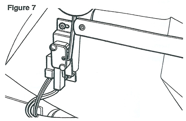
3. Pull the door lock release handle and the switch should energize and activate the central locking motors of all four doors to the unlocked mode. If the microswitch is faulty the driver's door central locking motor will be operated manually only but the motor of the other doors will remain locked.
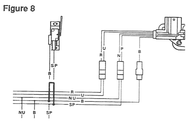
4. As a final check press the centre console switch to the doors locked position, remove the two leads from the micro switch and connect together, see figure 8. This should activate the central door locking motors to the unlocked position thus indicating a faulty microswitch.
Replacing central door locking motor
1. With the door window in the raised position, disconnect the vehicle battery.
2. Remove door casing.
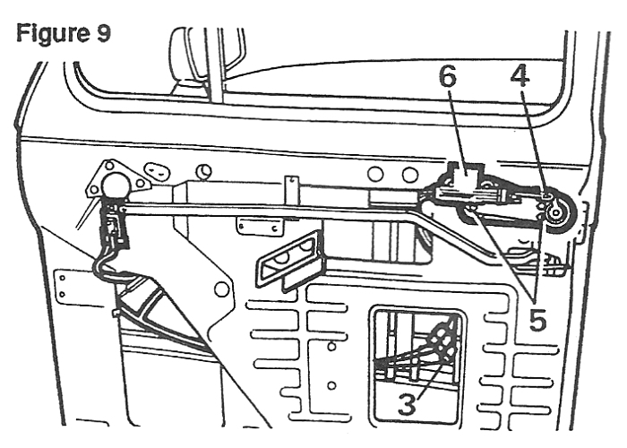
3. Disconnect central locking motor wiring plugs, See figure 9.
4. Release retaining clip and disconnect Connecting rod from door handle.
5. Remove three nuts and washers securing locking motor mounting plate to door handle studs.
6. While supporting the door handle, remove the locking motor assembly through the bottom aperture of the door panel.
7. Refit in reverse order.
Replacing central locking control box
1. Disconnect battery.
2. Remove right hand radio speaker/grille from fascia.
3. Pivot down fuse box to facilitate next operation.
4. Disconnect electrical plug and earth lead from control box, see figure 10.
5. Unscrew retaining nut and remove control box from vehicle bulkhead through radio speaker aperture.
6. Replace in reverse order.
Replacing driver's door microswitch
1. Disconnect battery.
2. Remove door casing.
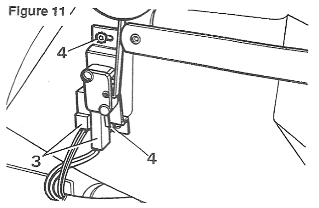
3. Disconnect the two leads from microswitch, see figure l1.
4. Remove two retaining screws and detach microswitch, complete with mounting bracket.
5. Fit new microswitch in reverse order ensuring it is correctly adjusted. With the interior door handle in the closed position the door release linkage should just abut the switch lever, see figure 11.

WHERE TO BUY THE SPARE PARTS
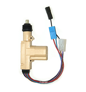
5wire/master Central Locking Door Motor (Solenoid/actuator) to equip front doors (driver's door only till 1995, 2 front doors from 1996)
Wolf

2wire/slave Central Locking Door Motor (Solenoid/actuator) to equip rear doors
wolf
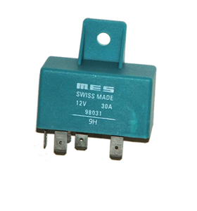
Central Locking relay
Wolf
The One Stop Part Shop
Note: Central locking system kits and other brand actuator motors can be found at a fraction of the cost but need slight modifications to fit the Fairway. Search ebay.co.uk.